A second RF engineer on your coverage project
For integrators who want help with the design, the measurements or the commissioning. Scoped and quoted per project.
Four services, and what you receive
Coverage design
Link budgets and DAS layouts for your building or tunnel.
You receiveA design note: link budget, layout on your plans and a bill of materials, ready for your own offer.
Site measurement
Donor and in-building signal levels, before and after installation.
You receiveA measurement report with the readings marked on your floor plan.
Commissioning support
Band plan, gain and alarm settings configured with your installer, on site or remotely.
You receiveA commissioning record per unit: settings, levels and alarms.
Selection and documentation
The repeaters, DAS and passive parts that fit the design.
You receiveA bill of materials with datasheets and test data for your project file.
How a project runs
From your plans to a commissioned system.
- 01
Send plans and requirements
Floor plans, the networks to cover, and the outdoor signal if it has been measured.
- 02
First assessment
A first product selection, a first link budget where the site needs one, and the list of what we still need from you.
- 03
Site measurement
Donor signal level and quality, and in-building levels where the design needs them.
- 04
Design
Link budget, layout on your plans and a bill of materials.
- 05
Commissioning
Settings, levels and alarms configured with your installer; levels measured against the design and recorded per unit.
The work on site and at the desk
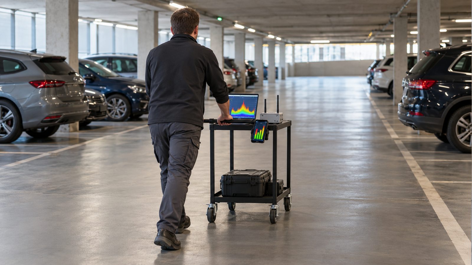 Illustration
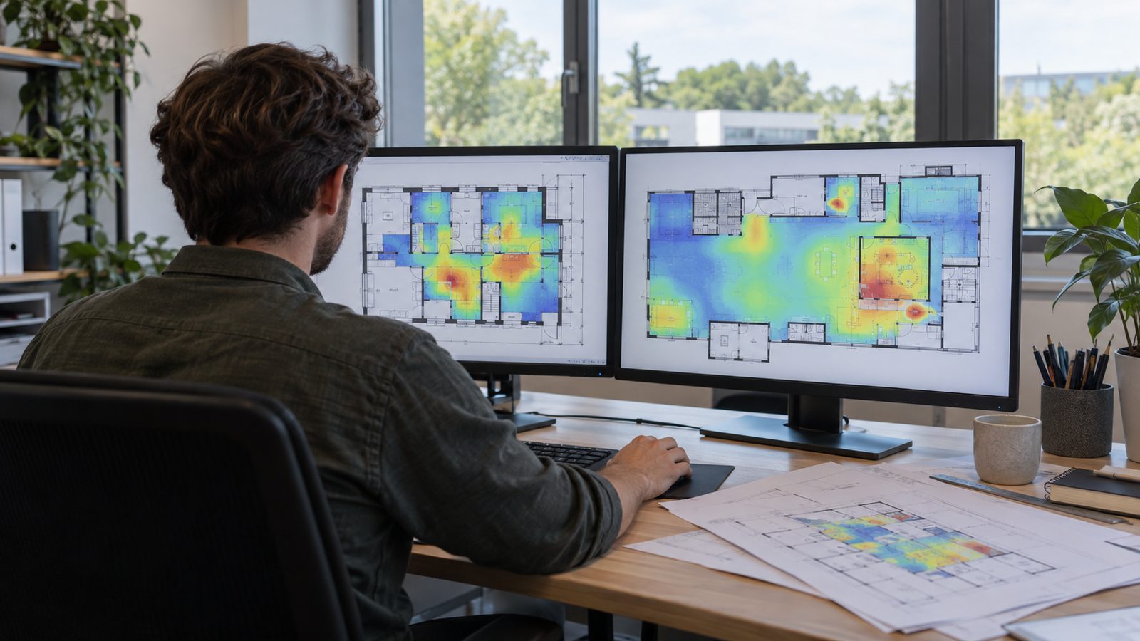 Illustration
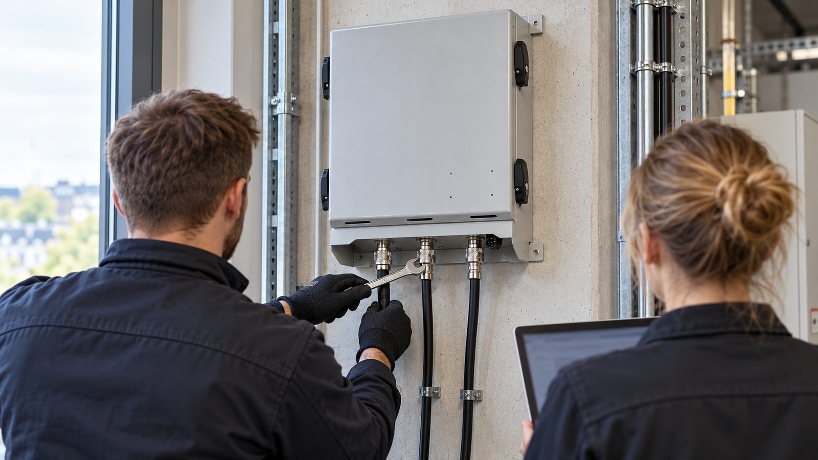 Illustration
s of typical sites and work, not of a specific installation.
How the systems fit together
Four typical architectures and the parts we supply in each. Every project is designed for its own building or tunnel.
Show the four architecturesHide the four architectures
Supplied by Rays CoverageFrom the operator or the integrator
Notes from the field
General RF practice that decides whether a coverage system works on the day it is switched on. None of it depends on whose equipment you use.
Isolation before gain
A repeater amplifies whatever reaches its donor port, including its own output leaking back from the service antennas. If the isolation between donor and service antennas is not at least 10 to 15 dB above the gain, the loop oscillates and the repeater disturbs the network or shuts itself down. Measure isolation on site before you set the gain.
Keep uplink gain in check
Excess uplink gain in a repeater or DAS raises the noise floor at the donor cell. The macro cell then hears every user in its area less well, not only those inside your building. Set uplink gain from the link budget and balance it with the downlink, rather than running at maximum. Keep the uplink noise that the repeater adds at the donor cell well below the noise floor of the base station itself, for a rise of about 1 dB or less.
Seven more notes
Check donor quality, not only level
A strong donor signal can still be a poor one: several cells of similar strength with no dominant server, or high interference, are amplified as they are. Measure quality and the serving cell at the donor position, and point the donor antenna at one chosen cell.
Count every passive loss
Combiners, POIs, splitters, couplers, jumpers and cable runs each take their share before the signal reaches an antenna. Put each one in the link budget at its datasheet value, with cable lengths from the real route, not the straight line. Small losses added up decide whether the farthest antenna is still useful.
Connectors decide PIM
Passive intermodulation usually starts at a connector, not inside a component. Keep mating faces clean and dry, tighten to the specified torque with a torque wrench, and avoid mixing connector metals and platings. A PIM source found after commissioning is far harder to locate than one prevented during installation. In a shared system, third-order products of downlink carriers can also fall into an uplink band, for example in Band 20 and Band 8, and raise the uplink noise floor for every operator.
Commission and document
Set and record the gain per band and per direction, check that every alarm reaches the management system, and measure levels at agreed points against the design. Keep the settings and readings with the as-built drawings: they are the reference for every later fault-finding visit.
Tunnels: remote units or radiating cable
Radiating cable gives even coverage along the bore and suits curves and confined sections, but its longitudinal loss limits how far one feed point reaches. Fibre-fed remote units with antennas put amplification where it is needed and keep the long runs on fibre, at the cost of more active equipment and power points in the tunnel. Many tunnels combine the two.
Keep critical comms and cellular apart
When critical-communications and cellular bands share a system, intermodulation and wideband noise from one can desensitise the other. Where that matters, separate the paths with filtering, or with separate amplifiers and antenna branches. Decide it at design stage, not after the first complaints from the radio users. For example, the second harmonic of a TETRA downlink at 390–395 MHz falls at 780–790 MHz, overlapping the 700 MHz downlink band.
Overlap zones at entrances and portals
Where the direct signal from the base station and the amplified signal overlap, the extra delay through repeater and fibre (several microseconds in a digital repeater, about 5 µs per km of fibre) should stay within the cyclic prefix, about 4.7 µs for LTE and 2.3 µs for 5G NR at 30 kHz subcarrier spacing, or one of the two signals should dominate by 10 dB or more. Limit that zone with antenna placement and check it during commissioning.
First-pass path loss and range estimate — free
Tell us about the site
A few answers are enough for a first product selection.
Planning a product line under your own brand? Use the OEM / ODM form.
- A product selection for the site
- A first link budget where the site needs one
- The list of what we still need from you, such as floor plans or donor measurements
You can attach floor plans here, or send them by email later.