Repeaters, DAS and RF components
Four product families. Each can be adapted to your band plan, power class and enclosure.
Other bands and regions on request: 617 MHz – 5.9 GHz, VHF 136–174 MHz, UHF up to 512 MHz, 700 MHz PPDR broadband; DMR and P25 on VHF and UHF.
Product families
Three power classes, one management stack
Cellular repeaters and bi-directional amplifiers for TETRA, DMR and P25, from 13 to 43 dBm.
Use it when a usable outdoor signal exists but does not reach inside the building, car park or tunnel.
Enclosures, power classes and functions
- DoesAmplifies selected cellular bands, or TETRA, DMR and P25, between a donor antenna and the service antennas, with digital band-selective filtering.
- BuiltThree power classes in wall-mount, 2U rack or cast-aluminium outdoor enclosures, up to 5 bands per unit.
- ManagedGain adjustable over 31 dB in 1 dB steps; per-band level and VSWR monitoring, locally, or remotely over an LTE modem or a WiFi module that joins the site network.
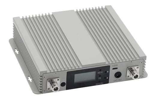
| Low power13–23 dBm | Typically one car-park level, or one floor fed from a donor antenna or a DAS branch. Wall-mount, LCD. |
|---|---|
| Medium power27–33 dBm | Typically a multi-floor office or hospital building, or the feed of a passive DAS. Wall-mount or 2U rack. |
| High power37–43 dBm | Typically road and rail tunnels and large halls, or the donor of a larger system. Cast-aluminium outdoor enclosure. |
Typical uses only: the right class follows from the link budget for your site.
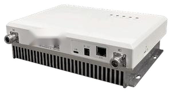
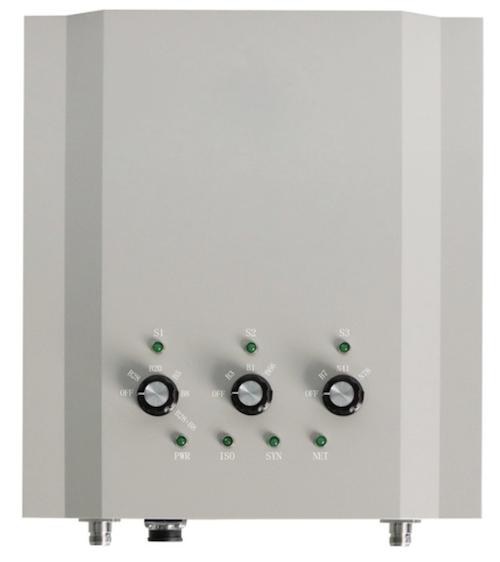
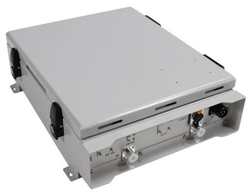
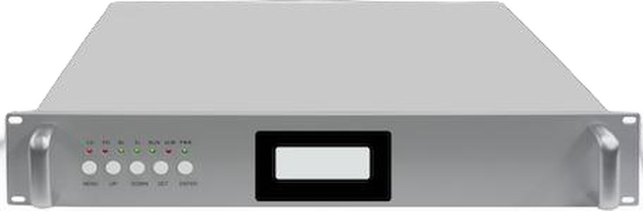
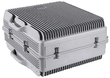
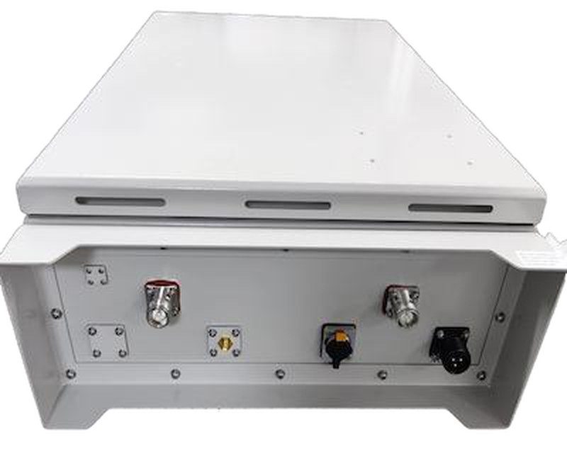
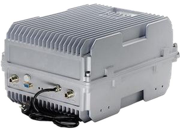
Cellular repeaters for 2G to 5G NR and bi-directional amplifiers for TETRA, DMR and P25. Digital band-selective, adjustable bandwidth, per-band level and VSWR monitoring, local WiFi web UI and remote management.
See the 105 models in the catalogue →
Request a build specification →The passive side of the system
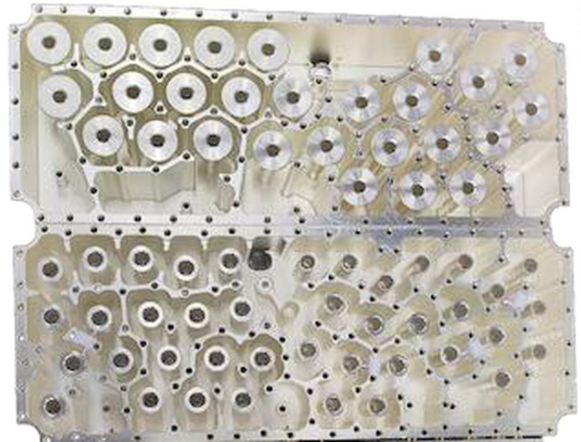
Combiners, duplexers, multi-operator POI and low-PIM passive components for in-building and tunnel systems.
Use it when several operators or services share one antenna system, or bands must be combined or separated around a repeater or DAS.
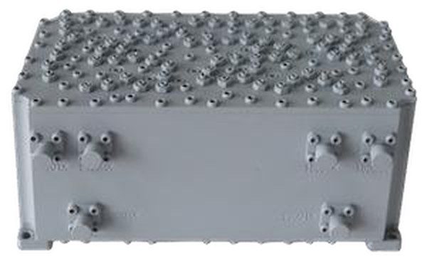
Combiner types, POI and passive specifications
- DoesCombines, separates and splits bands between the signal sources, the active equipment and the antennas; POI with 1, 2 or 4 antenna ports.
- BuiltSAW for low power, dielectric for medium power, cavity for high power; for the cavity combiners and POI, third-order PIM below −153 dBc at 2 × 43 dBm; other models per datasheet.
- AdaptedCombiners matched to your band plan; wideband passive components for 136–520 MHz and 614–6000 MHz, with N, 4.3-10 or 7/16 DIN connectors.
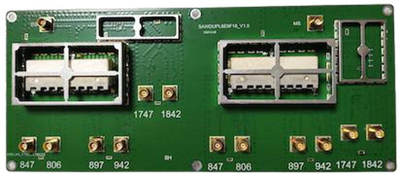
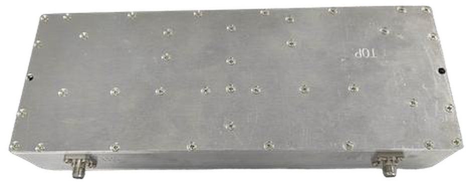
See the 16 models in the catalogue →
Request passive component datasheets →Fibre-fed distributed antenna systems
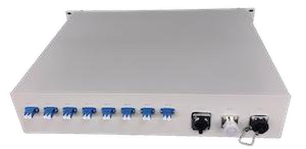
A 2U master unit with 8 optical remote ports, and remote units from 100 mW to 20 W.
Use it when a large building, campus or long tunnel needs coverage in more places than one repeater and a passive network can reach.
Remote units and output powers
- DoesCarries the signal from a base station or donor repeater over fibre to remote units placed where the coverage is needed.
- BuiltMaster unit in a 2U rack; remote units in ceiling, wall-mount or outdoor enclosures; the indoor-only models can also take DC over hybrid fibre.
- ManagedRadio over fibre, analogue or digital; remote units share the controller and management stack of the repeaters.
- BandsAs for the repeaters, including TETRA 380–400 MHz, per remote-unit model.
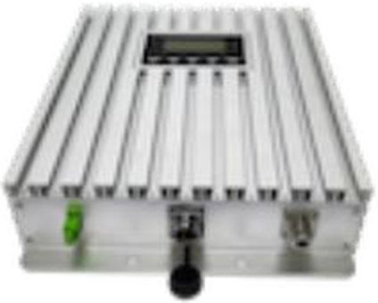
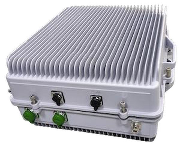
- Master unit — 2U rack, 8 optical remote ports
- Remote-unit output powers — 100 mW (20 dBm), 500 mW (27 dBm), 2 W (33 dBm), 10 W (40 dBm), 20 W (43 dBm)
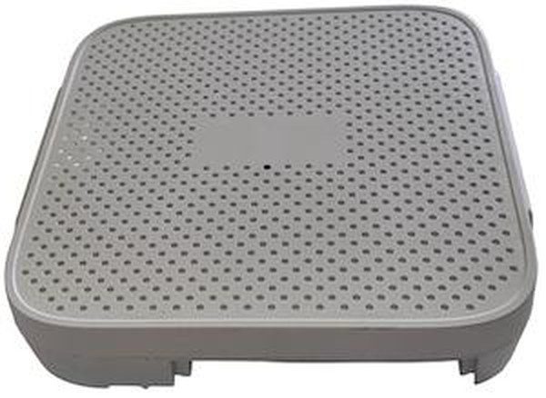
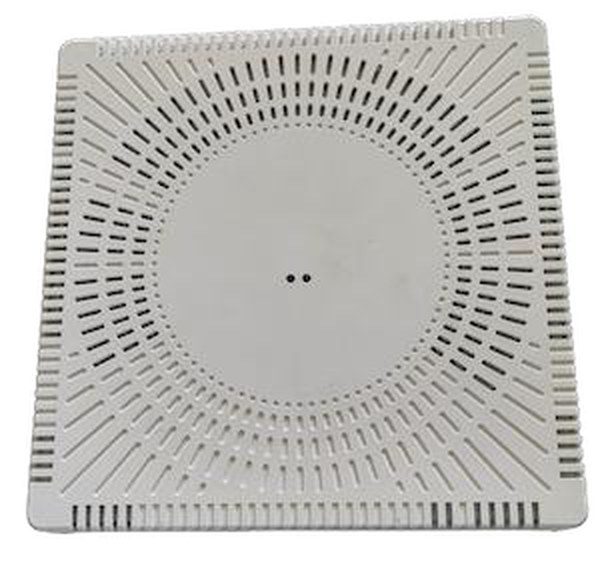
- Remote-unit enclosures — ceiling-mount with a discreet indoor finish, wall-mount for floors and car parks, outdoor enclosure for campuses and tunnels
- Per model — optical budget, maximum fibre length and MIMO support are stated in the datasheet and in the quote
See the 28 models in the catalogue →
Design a DAS with us →Microwave hops into places the macro network cannot reach
A donor unit and one or more remote units carry the cellular band over a microwave link.
Use it when a village, valley or remote site has neither fibre nor line of sight to the macro network; for a mine or long tunnel, the hop ends at the entrance and a DAS or radiating cable takes over inside.
Multi-hop links and how they work
- DoesThe donor unit moves the cellular band onto a microwave link; the remote unit converts it back and radiates it in the coverage area.
- BuiltA donor unit near the base station and one or more remote units, in single-hop or multi-hop configurations.
- AdaptedThe number of hops and remote units follows from your link plan and the terrain between the sites.
- BandsCellular bands as for the repeaters; link frequency per link plan and its spectrum licence; the donor unit is installed in agreement with the operator.
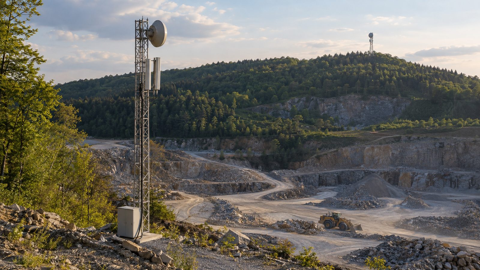
Single-hop and multi-hop configurations for rural villages, mountain roads, the entrances of mines and long tunnels, and temporary coverage.
Each family in its typical site
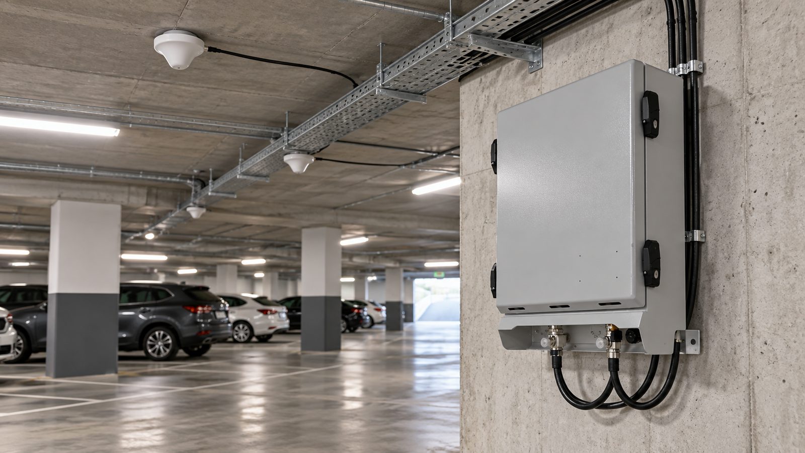 Illustration
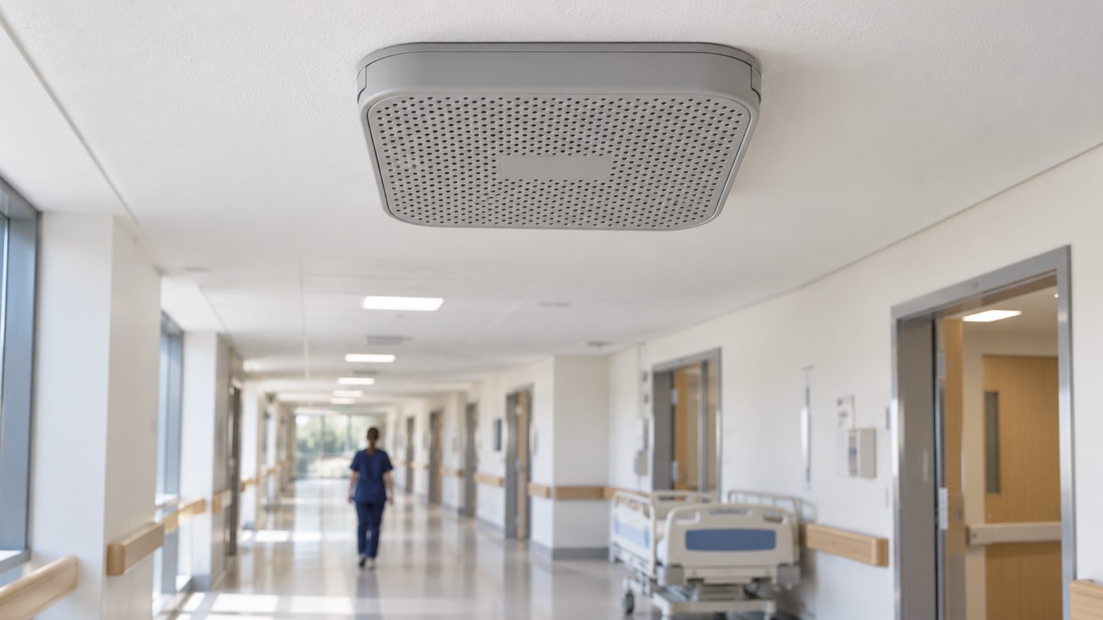 Illustration
 Illustration
s of typical sites and work, not of a specific installation.
Specifications by product family
Full datasheets per model are available on request. Datasheets, block diagrams, mechanical drawings, interface descriptions and the test record of every unit come with the delivery. Request a quote →
Repeater specification table
| RF repeaters | Low power | Medium power | High power |
|---|---|---|---|
| Output power | 13–23 dBm | 27–33 dBm | 37–43 dBm |
| Maximum gain, downlink / uplink (typical) | 75 / 65 dB | 80 dB | 95 / 90 dB |
| Noise figure at maximum gain | ≤ 8 dB | per datasheet | ≤ 5 dB |
| Gain adjustment range | 31 dB in 1 dB steps | 31 dB in 1 dB steps | 31 dB in 1 dB steps |
| Level control | Digital ALC; donor/service isolation check at start-up; gain lowered automatically on oscillation; details per model in the datasheet | ||
| System delay | ≤ 4.5 µs digital band-selective; ≤ 2.0 µs wideband | ||
| Bands per unit | up to 5 | up to 5 | up to 5 |
| Control | Local: LCD and keypad, web page over WiFi, RJ45/USB. Remote: LTE modem, or a WiFi module that joins the site network | ||
| Alarm interfaces | Per build specification (alarm contacts, Ethernet/SNMP) | ||
| Supply | AC 100–240 V (external adapter on the low-power models); DC and backup power per build specification | ||
Active DAS remote units: specification table
| Active DAS remote unit | Placement | Power options | Transport |
|---|---|---|---|
| 100 mW (20 dBm) | Indoor | AC 100–240 V or DC over hybrid fibre | Radio over fibre, analogue or digital |
| 500 mW (27 dBm) | Indoor | AC 100–240 V or DC over hybrid fibre | Radio over fibre, analogue or digital |
| 2 W (33 dBm) | Indoor | AC 100–240 V or DC over hybrid fibre | Radio over fibre, analogue or digital |
| 10 W (40 dBm) | Indoor and outdoor | AC 100–240 V | Radio over fibre, analogue or digital |
| 20 W (43 dBm) | Indoor and outdoor | AC 100–240 V | Radio over fibre, analogue or digital |
Combiners and passive components: specification table
| Combiners / duplexers | SAW (low power) · dielectric (medium power) · cavity (high power) |
|---|---|
| Multi-operator POI | 1, 2 or 4 antenna ports |
| Passive intermodulation | cavity combiners and POI: third-order PIM below −153 dBc at 2 × 43 dBm; other models: stated in the datasheet per model |
| Connectors | N, 4.3-10 and 7/16 DIN |
| Frequency ranges | 136–520 MHz and 614–6000 MHz wideband passive components |
How to specify a combiner or POI
A combiner or POI is built for one system. With these points we can propose a filter type and a port layout.
What to send us
- Operators and bands — each operator or service and the bands it brings, uplink and downlink
- Inputs and outputs — the number of inputs, and the number of antenna ports
- Power — the maximum power on each input
- PIM — your PIM requirement and the test power it refers to
- Connectors — N, 4.3-10 or 7/16 DIN
- Mounting — indoor or outdoor, and rack, wall or cabinet mounting
- Monitoring — test or monitoring ports, or other monitoring needs
Controller, remote management and software
The same controller and management stack in every repeater and remote unit, whatever the power class.
Mainboard, management interface and screenshots
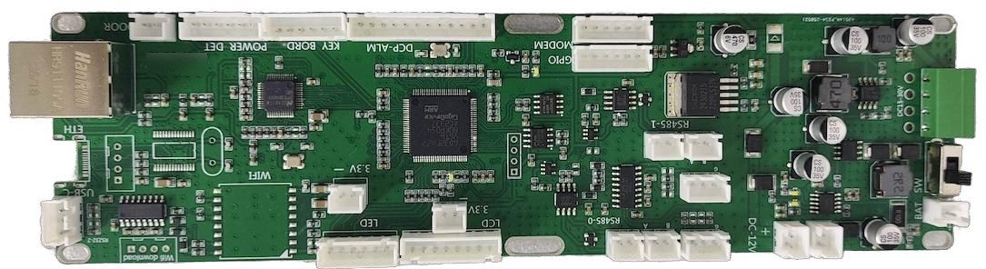
Controller mainboard
Drives the LCD/LED panel and alarms; RS-485 ×2, RS-232, Ethernet, USB, WiFi and GPIO on board; 12 V input. The same controller across all power classes.
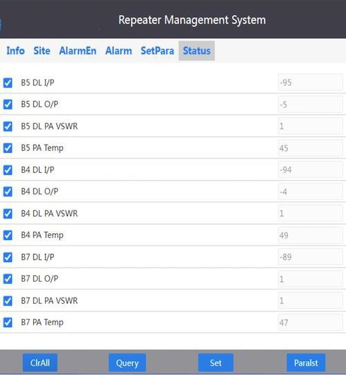
Remote-management interface
Plug-in LTE modem with SIM slot, so a unit reports to the management server without a site network; or a WiFi module that joins the site network.
Local and remote management
- Local — LCD and keypad, RJ45, USB or WiFi: web UI in any browser, or the desktop management application
- Remote — LTE modem, or a WiFi module that joins the site network, to a management server with a web console, hosted within the EU or on your own server
- Per-band input/output level, PA VSWR and temperature; alarms, polling, logs
- Site and equipment lists, user roles, operation history
- Roadmap, in development — an open interface into the integrator's own monitoring platform

RF power amplifier modules (up to 24, 33 and 43 dBm output) and the controller mainboard are also supplied separately for your own designs: OEM / ODM supply →
Request a quote
The product family, the bands and the power class are enough for a first quote; a quantity range helps us prepare it.
Planning a product line under your own brand? Use the OEM / ODM form.
- A quote for the products you name
- The datasheets of the models in the quote
- The list of what we still need from you, such as the band plan or site details
You can attach a band plan, drawings or a bill of materials here, or send them by email later.