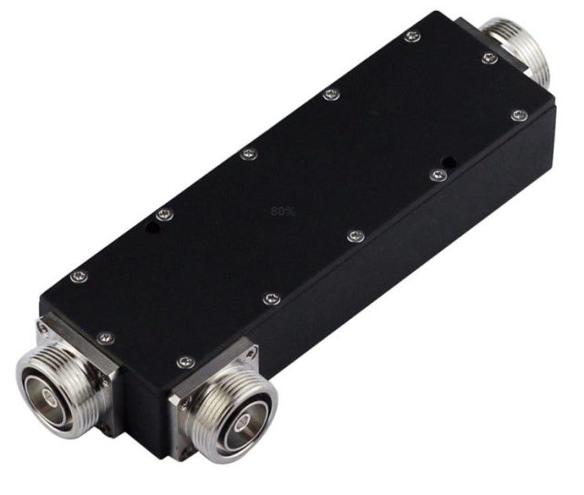
Directional coupler 5 dB, N-female RC-PAS-018
Directional couplers are most frequently constructed from two coupled transmission lines set close enough together such that energy passing through one is coupled to the other. This technique is favoured at the microwave frequencies where transmission line designs are commonly used to implement many circuit elements. However, lumped component devices are also possible at lower frequencies, such as the audio frequencies encountered in telephony. Also at microwave frequencies, particularly the higher bands, waveguide designs can be used. Many of these waveguide couplers correspond to one of the conducting transmission line designs, but there are also types that are unique to waveguide.
| Connector | N/Female |
|---|---|
| VSWR | < 1.25 |
| Insertion Loss | < 2.15 |
| Power Rating | 500W |
Specifications
| Frequency | 698 - 2700MHz |
|---|---|
| Attenuation | ± 1 |
| Insertion Loss | < 2.15 |
| VSWR | < 1.25 |
| PIM (IM3) | < -150dBc @ + 43dBm*2 |
| Isolation | > 25 |
| Power handling | 500 W |
| Impedance | 50 Ohm |
| Operating temperature | - 40°C to + 75°C |
| Storage temperature | - 40°C to + 85°C |
| Relative Humidity | 5% - 95% |
| Applications | IP65 |
| Connector type | N - Female |
| Weight | 0.68Kg |
| Dimension | 200.5*68.8*32mm |
Figures are those stated for the standard model. Bands, power and options can differ per build: for your project we confirm them in a written build specification, and every unit ships with its own test record. Datasheets are available on request.
Other models in this family
Request a quote
The product family, the bands and the power class are enough for a first quote; a quantity range helps us prepare it.
Planning a product line under your own brand? Use the OEM / ODM form.
- A quote for the products you name
- The datasheets of the models in the quote
- The list of what we still need from you, such as the band plan or site details
You can attach a band plan, drawings or a bill of materials here, or send them by email later.