Microwave imaging research on the 8T8R platform
Eight coherent receive channels, a stepped-frequency sweep and an antenna switch matrix are the ingredients of a multistatic microwave imaging system. Before building a bench, we model the whole chain in full-wave simulation: antennas, coupling medium, tissue-like phantoms and the image reconstruction.
Status Research demonstration with simulation data only. No measurement on the 8T8R board has been made for this work; no image on this page is a measurement. Not for use on people; not intended for diagnosis, monitoring or treatment.
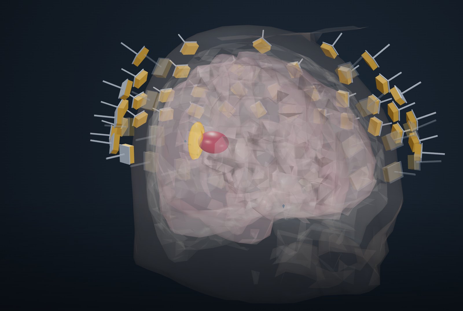
What is simulated
The same steps a bench would follow, each one modelled.
Antennas around the phantom
A head-worn conformal array or a ring around a breast phantom, behind a coupling pad. Eight transmit and eight receive channels are multiplexed to 32 or 64 antennas with RF switches.
Stepped-frequency, every pair
Each transmitter steps through the band while all receivers record; the result is a complex transfer function for every transmit–receive pair and frequency.
FDTD with tissue properties
Finite-difference time-domain models in 2-D and 3-D, with frequency-dependent tissue permittivity and conductivity and the antenna structures included.
Differential reconstruction
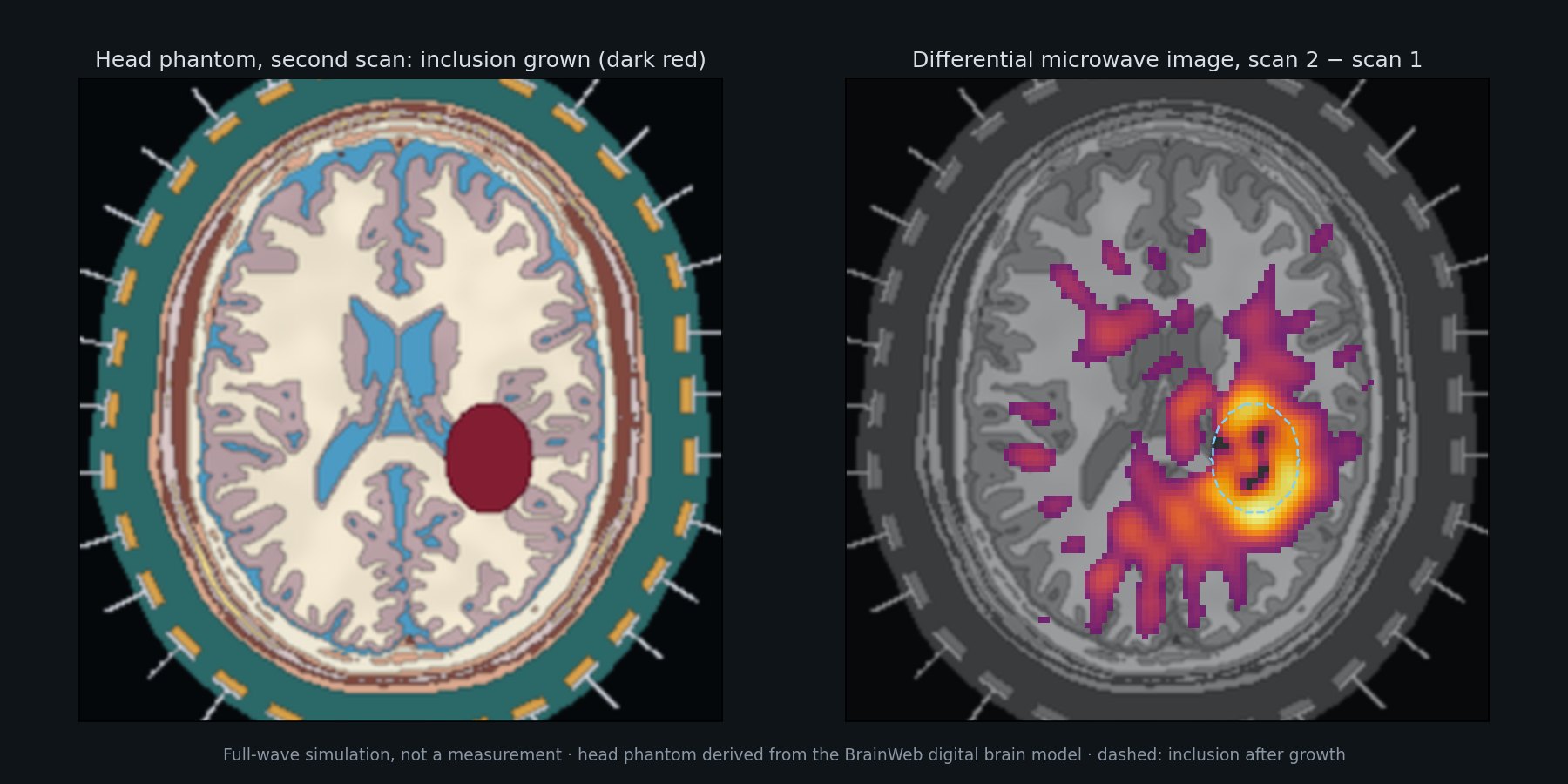
Two scans of the same phantom are compared and a back-projection image of the change is formed. The demonstration shows the scans, the difference and the raw data.
Run a simulated scan in the browser
Opens in a new window. Best on a desktop browser; the 3-D view needs a connection to load its graphics library.
Localising a dielectric change
An axial slice and a 3-D head phantom derived from the BrainWeb digital brain model. A high-permittivity inclusion grows between two scans; the differential image shows where the change is. Simulation based on the BrainWeb digital brain phantom (see Data sources).
Single scans and size change
Phantoms of low and scattered fibroglandular density with a 10 mm high-permittivity inclusion, and a differential case in which the inclusion shrinks from 10 to 6 mm.
What the simulations show so far
Stated with their limits. Analyses were written down before they were run, and are reported whether or not they met their criteria.
Changes can be localised
In 2-D full-wave head-phantom simulations with modelled electronic errors, a growing high-permittivity inclusion is usually separable from no change and localised near the changed region. This holds under the simulation's own error model.
Mechanical repeatability
When the antenna array is moved by 1 mm in the full-wave model, the false change it creates is as strong as the real change we look for. Electronics matter less than keeping the antennas still relative to the head between scans.
Not yet established
A simple phase model of array motion did not hold in full-wave checks, and the 1 mm simulation grid has not converged against a 0.5 mm grid. Results under realistic motion are therefore not yet quantitative.
Phantoms and references
The head phantoms are derived from the BrainWeb simulated brain database (McGill University, Montreal Neurological Institute): brainweb.bic.mni.mcgill.ca/brainweb. Only our own simulation results are shown; the BrainWeb data files are not redistributed. The breast phantoms are generated procedurally by us.
- C.A. Cocosco, V. Kollokian, R.K.-S. Kwan, A.C. Evans, “BrainWeb: Online Interface to a 3D MRI Simulated Brain Database”, NeuroImage 5(4), part 2/4, S425, 1997.
- R.K.-S. Kwan, A.C. Evans, G.B. Pike, “MRI simulation-based evaluation of image-processing and classification methods”, IEEE Transactions on Medical Imaging 18(11):1085–1097, 1999.
- R.K.-S. Kwan, A.C. Evans, G.B. Pike, “An Extensible MRI Simulator for Post-Processing Evaluation”, Visualization in Biomedical Computing (VBC’96), LNCS 1131, Springer, 1996, pp. 135–140.
- D.L. Collins, A.P. Zijdenbos, V. Kollokian, J.G. Sled, N.J. Kabani, C.J. Holmes, A.C. Evans, “Design and Construction of a Realistic Digital Brain Phantom”, IEEE Transactions on Medical Imaging 17(3):463–468, 1998.
Research demonstration · simulation data only · not measured · not for use on people · not intended for diagnosis, monitoring or treatment.