Request a quoteFrom €1,200 excl. VAT

Utility detection: find the pipes, cables and structures before you dig.

The plans show the public networks, roughly. They do not show the private drain, the abandoned line, the old tank or the foundation of the building that stood here before. We find them, mark them on the ground and give you their depth.

Belgium and neighbouring regionsReport in EN · FR · NLFrom €1,200 excl. VAT; travel listed separately in the quote
Illustration: our SHRS ground radar pulled along a street, its odometer wheel on the asphalt, past utility lines sprayed in paint and a manhole
Illustration

What we find

Typical depth and the antenna we bring. The ground decides the rest; we say so before quoting.

Pipes and cables

Metal, concrete and clay pipes, ducts and cable runs before excavation.

Typical depth
0.3 – 4 m
Antenna
400 / 200 MHz

Tanks and manholes

Buried fuel or water tanks and their covers under asphalt or paving.

Typical depth
0.3 – 3 m
Antenna
400 MHz

Old foundations

Footings and wall lines of demolished or undocumented buildings.

Typical depth
0.5 – 4 m
Antenna
400 / 200 MHz

Voids and cavities

Settlement voids, washed-out zones, cellars and residual cavities.

Typical depth
0.5 – 6 m
Antenna
400 / 200 MHz

Galleries and deep pipes

Service galleries and deep pipelines, located after a short test section.

Typical depth
2 – 8 m
Antenna
200 MHz, feasibility test first

Deep or large targets start with a feasibility test: a short test section decides whether a full survey makes sense.

KLIP · KLIM-CICC

Start with the utility plans, then decide

In Belgium the network operators' plans are requested through KLIP in Flanders and KLIM-CICC in Wallonia and Brussels. Ask for them first. Radar is for what the plans do not settle.

01

What the plans give you

The public networks declared by their operators: gas, water, electricity, telecom and sewers, with an indicative position.

02

What they leave open

Private pipes and drains on the plot, abandoned lines, old tanks and foundations, and the real position and depth of what is drawn.

03

Where radar comes in

We survey with the plans in hand, confirm or correct the positions on the ground, and mark what was on no plan.

What you receive

  • The findings marked on the ground with spray paint or pegs, included in the price
  • A depth-coloured plan as a PDF in Belgian Lambert 2008 coordinates, tied to manholes and fixed points
  • Annotated radargrams, with the depth and a confidence grade for every target
  • A report in PDF and DOCX; data files on request
Illustration: crossing utility lines sprayed on paving stones, and a survey peg
Illustration

The limits, for this kind of survey

01

Small plastic pipes

Below about 50 mm, or empty, they often give no usable reflection.

02

Wet clay and saline soil

They absorb the signal. Reach can drop to a third of what the same antenna achieves in sand.

03

Depth is an estimate

It comes from the wave velocity in your soil. We calibrate where we can and state the uncertainty.

04

Deep pipes and galleries

Below a few metres the ground sets the limit; we start with a test section at 200 MHz.

Projects of this kind, anonymised

Client names, addresses and locations withheld.

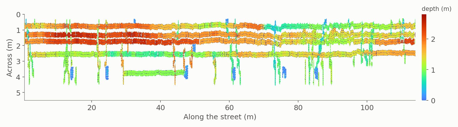
Pipe depth map along a street, from the radar profiles
Road · Sewer network

Pipe depths along a street, tied to the manholes

Profiles along the street, tied to the sewer manholes visible on the surface; pipes picked on each radargram and plotted on a depth map next to the road-surface image, so it is clear which manhole feeds which run. Median depth 1.37 m, standard deviation 0.52 m — a spread worth knowing before deciding where to dig.
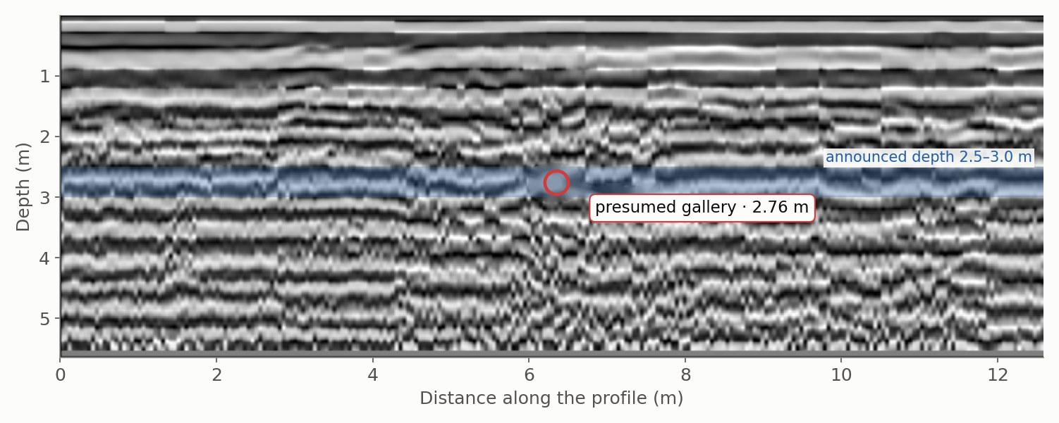
Processed 200 MHz radargram; the presumed gallery is picked at 2.76 m, inside the announced 2.5–3.0 m depth band
Utility gallery

A buried gallery located, at the limit of what the ground allowed

Forty 200 MHz profiles over a plot crossed by a masonry gallery announced at 2.5–3 m. The wave velocity was calibrated from the data (0.113 m/ns) and the useful depth measured on site (2.83 m), so the target sat right at the limit. The gallery was located on 8 profiles from a local break in the layering, not a textbook hyperbola: its axis runs 3.4 m from the route drawn on the plan, parallel to it within 0.5°, at 2.46–2.92 m depth, inside the no-build zone. The report states the fit scatter (± 0.19 m) and what it does not cover.

Time-slice overlay on the site map showing two parallel pipes and a crossing
Urban road

Two parallel pipes and a crossing, on the map

Time slices at 0.5 m overlaid on the site map: two parallel pipes follow the road and a third crosses them — a plan the works team could use directly.

In our project log

SiteTaskAntenna · dataStatus
Utility galleryLocate a buried service gallery along its presumed route200 MHz · 40 profilesSurveyed · gallery located
Urban utility networkPipe inspection—Surveyed
Industrial sitePipe inspection, manhole-tied profiles70 profilesSurveyed
Urban roadPipe inspection with a commercial multichannel array system8 channels · positionedSurveyed
Utility networkUtility pipe mapping in gridded swaths with a commercial multichannel array system, delivered as a pipe depth map10 channels · gridded swathsSurveyed
Electrical substationLocating the conductors of the grounding grid with a commercial multichannel array systemGridded surveySurveyed

Status: Surveyed — carried out by us on site. Commissioned — ordered by the client, survey still to be carried out.

Budget

From €1,200 excl. VAT for a single target, such as a tank cover or one or two manholes; from €2,000 excl. VAT for one plot or line. Several zones or industrial sites are quoted.

Every quote lists field time, processing, reporting and travel separately.

Request a quote

Tell us the site and the target. An engineer replies within one working day, with a fixed price or a question.

* required

Reply within one working day · no obligation

Or call +32 (0) 491 08 61 09

Plans and photos help: you can send them in reply to our first email.

We use these details only to answer your request. Privacy policy

Frequently asked

Do I still need the KLIP or KLIM-CICC plans?

Yes. Request them first: they list the public networks. Radar then checks positions and depths on the ground and finds what is on no plan.

Can you find plastic pipes?

Often, with limits. Plastic pipes under about 50 mm, or empty ones, may give no usable reflection; the report gives a confidence grade for each target.

How deep can you see a pipe?

Typically 0.3 to 4 m with the 400 and 200 MHz antennas, depending on the soil. For deep pipelines and galleries we start with a test section.

Do you mark the findings on the ground?

Yes. Pipes, cables and other findings are marked on site with spray paint or pegs, and this is included in the survey price. The plan follows as a PDF in Belgian Lambert 2008 coordinates.