Request a quoteFrom €1,200 excl. VAT

Concrete and structures: see the rebar, the thickness and the voids before you drill.

You need to core, anchor or saw through a slab without hitting a bar or a duct, or you want to know why a floor sags or a deck lets water through. The drawings are missing, or do not match what was built.

Belgium and neighbouring regionsReport in EN · FR · NLFrom €1,200 excl. VAT; travel listed separately in the quote
Illustration: our SHRS ground radar on an underground car park floor, along chalked rebar lines, next to a marked coring spot
Illustration

What we find

Typical depth and the antenna we bring. The ground decides the rest; we say so before quoting.

Rebar and slabs

Reinforcement layout, slab thickness and safe coring zones.

Typical depth
0 – 0.6 m
Antenna
900 MHz / 1.6 GHz

Layers, voids and moisture

Surface and structural layers, debonding, voids and wet zones in floors, decks and tunnel linings.

Typical depth
0 – 0.6 m
Antenna
900 MHz / 1.6 GHz

Deep or large targets start with a feasibility test: a short test section decides whether a full survey makes sense.

Processed radargram of a reinforced concrete slab: a row of small hyperbolas from the rebar below a continuous layer reflection
From a real survey

Reinforced slab: the rebar shows as a regular row of hyperbolas

Each bar the radar line crosses returns an arch-shaped echo. A row of evenly repeated arches is the reinforcement layer; the continuous line above it is a layer interface in the floor. The shape of the arches gives the wave velocity in the concrete, and from it the depth of the bars.

Processed radargram, not migrated, so the hyperbolas stay visible.

What you receive

  • Bars and ducts located in the zone where you will drill or core
  • Thickness maps of the slab or deck, zone by zone
  • Annotated radargrams, with the wave velocity or permittivity used for the depths
  • A report in PDF and DOCX
Illustration: rebar positions sprayed on a slab and a circle marking where to core, next to a core drill
Illustration

The limits, for this kind of survey

01

Below dense reinforcement

A tight rebar mesh reflects most of the energy; what lies under it may stay hidden.

02

Depth needs a velocity

Depths assume a wave velocity in the concrete; a core or a known thickness calibrates it.

03

Similar concretes

Two concretes cast against each other can give little contrast; such interfaces are reported as indicative.

04

Corrosion

Radar shows where to core or open up; it does not measure corrosion directly.

Projects of this kind, anonymised

Client names, addresses and locations withheld.

Thickness map of a car park floor slab, one block, measurement lines 0.3 m apart
Building · Underground car park

Slab thickness, moisture and void risk across a car park floor

Four zones on lines 0.3 m apart. For each block the report gave the structural layer thickness (block averages 26–35 cm, from 18 to 45 cm overall), the surface layer, moisture-risk areas beneath it and the risk of voids or debonding. A core through the 13 cm surface layer served as a check.
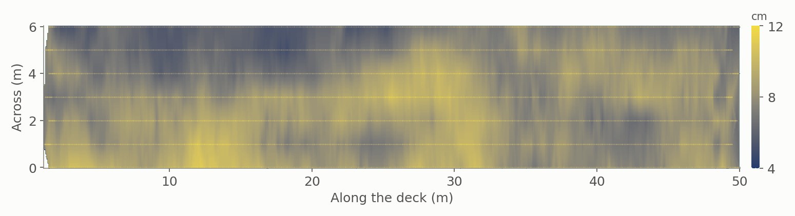
Asphalt thickness map over a 50 m bridge deck
Bridge · Hollow-core slab deck

Every layer of a bridge deck, read from the surface

Transverse and longitudinal lines on an orthogonal grid over the deck. On the reference profile: two asphalt layers of 11.8 and 9.2 cm, a 10.3 cm cast-in-place slab, a 6.9 cm slab top and the 44.8 cm void of the hollow core. The readings pointed to frequent debonding between layers and one zone with no concrete cover over the rebar. Ten cores were taken for calibration; the interface between the cast-in-place concrete and the slab gave little contrast and was reported as indicative only.

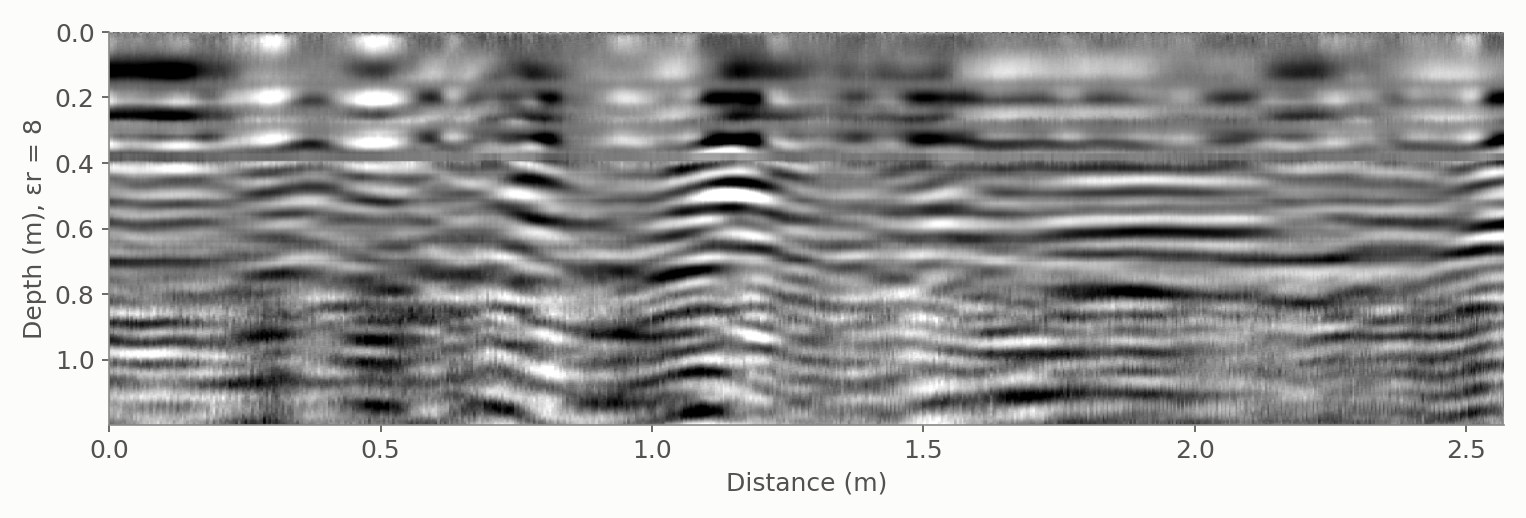
Radargram across the basement slab, depth axis for a relative permittivity of 8
Building · Residential basement

Rebar spacing that did not match the rest of the slab

Two basement levels scanned line by line. Slab about 17 cm thick, two rebar layers about 13 cm apart, bars mostly about 18 cm apart — but about 37 cm in part of the lower level. There the slab sagged locally, a wet zone showed beneath it, and a strong reflector at about 2.3 m pointed to the water table. Depths assumed a relative permittivity of 8, and the report says so.

In our project log

SiteTaskAntenna · dataStatus
Building basementReinforced slab: rebar, voids and moisture, with a full reportDual-frequency · ~100 lines at 0.3 mSurveyed
BridgeDeck on hollow-core slabs: layer thickness and voids, with cores taken for calibrationOrthogonal grid · transverse and longitudinal linesSurveyed
Metro tunnelTunnel lining thickness and reinforcement600 MHzSurveyed
BuildingRebar mapping in floor slabs—Surveyed
BuildingMoisture assessment of masonry walls—Surveyed

Status: Surveyed — carried out by us on site. Commissioned — ordered by the client, survey still to be carried out.

Budget

From €1,200 excl. VAT for a single zone; from €2,000 excl. VAT for a floor or a deck. Several zones and large structures are quoted per zone.

Every quote lists field time, processing, reporting and travel separately.

Request a quote

Tell us the site and the target. An engineer replies within one working day, with a fixed price or a question.

* required

Reply within one working day · no obligation

Or call +32 (0) 491 08 61 09

Plans and photos help: you can send them in reply to our first email.

We use these details only to answer your request. Privacy policy

Frequently asked

Can you tell us where it is safe to core?

Yes. We map the bars and ducts in the zone and show where coring avoids them.

Can you measure slab thickness from one side?

Yes, where the underside of the slab gives a reflection. A core or a known thickness calibrates the depth.

Do you survey bridge decks and tunnel linings?

Yes. Bridges and tunnels are surveyed as structures: layer thickness, reinforcement and voids, with cores for calibration where possible.

Can radar see corrosion?

Not directly. It shows where reinforcement and moisture make a closer look worthwhile.